Geology Reference
In-Depth Information
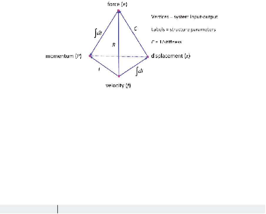
Figure 2. Tetrahedron of state showing the relations of state variables and the constitutive relations in
structural engineering (Paynter 1961)
from one energy domain is transferred to
another domain. The Gyrator modulus μ
defines the relation between effort and flow.
For the GY of Figure 1(a5),
e
tural systems, S
e
represents an external
force, and S
f
represents an input velocity to
the system. The causal stroke implies that
either the effort (force) or flow (velocity) is
generated by the source and is imposed on
the system. In either case, the half arrow is
pointing away from the source indicating
=
µ
and
f
2
1
1
=
µ
2
.
6.
Effort and flow sources (S
e
, S
f
) (Figures
1(b1) & 1(b2)):
These are active BG ele-
ments since they produce energy. In struc-
e
f
Table 1. Conversion of Bond graph elements and terminology to structural engineering
Bond graph term
Corresponding term in structural engineering
Units
Capacitance (C)
Inductance (I)
Resistance (R)
Transformer (TF)
Gyrator (GY)
Effort (
e
)
Flow (
f
)
Displacement
Effort source
S
e
Flow source
S
f
Power
Energy
E
Momentum
P
N / m
N s
2
/ m
N s / m
--
--
N
m / s
m
--
--
N m / s
N m
N s
Models member or spring stiffness
k
=
1 /
C
Models inertia effects, mass
m I
=
Models damping, friction or resistance forces
D R
=
Massless lever or participation factor in modal analysis
Mechanical gyrator or ideal DC motor
Force or torque
F t
e t
=
Velocity or angular velocity
u t
( )
( )
( )
=
f t
( )
A source that exerts a force on the system (e.g. an actuator)
A source that exerts a velocity on the system
Power
f dt
=
effort
×
flow
=
e
×
f
=
∫
E
e f dt
=
∫
P
e dt


Search WWH ::

Custom Search