Geology Reference
In-Depth Information
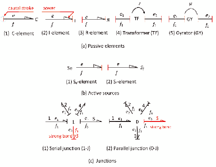
Figure 1. Bond graph elements: (a) passive elements (b) active sources (c) junctions
(effect). The small vertical line in Figure
a(1) is the causal stroke representing the
integral causality relation (constitutive equa-
tion). The half arrow defines the direction
of power flow (
power
=
e f
).
2.
I-element (Figure 1(a2)):
I-element models
inertial effects in structural systems, and
inductance effects in electrical or fluid sys-
tems. For a mass
m
subjected to a force
p
,
damper,
e
and
f
are related through a linear
relation (
e
=
f
). R-elements can have
the causal stroke at either ends.
4.
TF-element (Figure 1(a4)):
TF-element
can represent an ideal electrical transformer
or a massless lever. It can also represent the
mode shape at a point in the structure. TF-
element does not store or absorb energy. It
conserves power and transmits the factors
of power with power scaling as defined by
the transformer modulus r. The balance rela-
tion between the power variables for the
transformer of Figure 1(a4) is
e f
t
t
∫
∫
f
( /
1
m
)
e dt
( /
1
m
)
p dt
=
=
.
−∞
−∞
This relation represents the Newton's second
law of motion. Herein, the effort history is
integrated to generate flow thus I-element
receives effort (cause) and generates flow
(effect).
3.
R-element (Figure 1(a3)):
R-element mod-
els energy dissipation components, such as,
dampers, dashpots, electrical resistors and
valves or losses in fluid lines. For a linear
=
e f
,
1 1
2 2
5.
GY-element (Figure 1(a5)):
The gyrator
establishes the relationship between flow to
effort and effort to flow, gain keeping the
power on the ports the same. The simplest
gyrator is a mechanical gyroscope or an ideal
DC motor. Gyrators are used when power
which leads to
f
=
or
e
rf
=
( / )
1
r e
.
2
1
2
Search WWH ::

Custom Search