Biomedical Engineering Reference
In-Depth Information
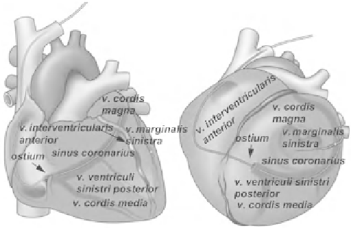
Fig. 12.5
Anteroposterior and left anterior oblique views of the
coronary venous system [ 82 ] (© 2012 Boston Scienti fi c Corporation or
its affiliates. All rights reserved. Used with permission of Boston
Scienti fi c Corporation)
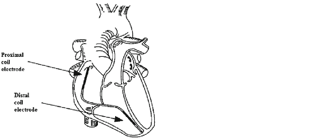
Fig. 12.4
Optimal position of the defibrillation lead in the right
ventricle [ 51 ] (© 2012 Boston Scienti fi c Corporation or its af fi liates.
All rights reserved. Used with permission of Boston Scientific
Corporation)
12.1.6 Implanting the Left Ventricular Lead
The left ventricular (LV) lead is positioned transvenously by
means of catheterization made by a long guiding sheath and a
mapping electrophysiological catheter. First, cannulate the
ostium of the coronary sinus. The diameter of the mapping
electrophysiological catheter is usually 6 F (or smaller), and
its distal end is equipped with a deflectable or flexible tip.
After removing the mapping electrophysiological catheter,
the route for lead positioning is formed. Take the coronary
angiogram with or without the help of a balloon occlusion
catheter. The angiogram visualizes the system of coronary
veins. Save the angiogram for later reference when dealing
with the venous anatomy. Risks connected to this intervention
are similar to those of any other catheterization procedure of
the coronary sinus. Some patients might show intolerance to
various types of contrast media. Figure
12.5
displays an
example of the coronary venous system. The coronary sinus
and its branches include the great cardiac vein (
v. cordis
magna
), the middle cardiac vein (
v. cordis media
), the poste-
rior vein of the left ventricle (
v. ventriculi sinistri posterior
),
and the left marginal vein (
v. marginalis sinistra
). Different
anatomic conditions among patients enable positioning of
the lead in one or more recommended places.
The guiding sheath helps to introduce the lead into the
venous system and helps to protect the LV lead during posi-
tioning of the other leads. To avoid thromboembolism in the
lead and the guiding sheath, flush the internal lumen of the
lead and the guiding sheath with heparinized physiological
solution before and during their usage. Introduce a suitable
guide wire to the lead through the distal electrode tip so that
the wire is projected less than 2 cm and check whether the
guide wire can be pushed easily through the lead's lumen.
12.1.4 Fixating the Passive Fixation Lead
The lead with the stylet introduced is advanced transvenously
to a place where it can be captured by the trabeculae. Where
the lead tines get embedded, the stylet is partially retracted.
Using fluoroscopy, check the stability of the lead in the tra-
beculae as the patient coughs and respires deeply on your
upon the clinician's instruction. If it is necessary to change
the lead position, advance the lead's pacing tine to the trabe-
culae by means of a straight stylet. It is necessary to pay
attention to the fact that all the leads must be positioned in
the healthiest heart tissue available.
12.1.5 Implanting the De fi brillation Lead
Apply the defibrillation lead using fluoroscopy; the stylet is
introduced to the lead so that its distal end is placed in the
right ventricular apex. Check whether the distal shock elec-
trode is positioned in the right ventricle under the tricuspid
valve (right ventricular apex) and that the respective proxi-
mal electrode (in case of dual-coil defibrillation leads) is sit-
uated at the superior vena cava and at the right atrial junction.
Correct function of the leads is dependent on their proper
position. The defibrillation lead also serves for pacing, so its
distal tip must be situated at the healthy myocardium in the
apex of the heart (Fig.
12.4
). Improper positioning might
cause movement of the lead and prevent the defibrillation
shock from incorporating the apex of the heart.