Biomedical Engineering Reference
In-Depth Information
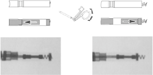
Fig. 12.3
Views of the active helix electrode [49] (© 2012 Boston
Scientific Corporation or its affiliates. All rights reserved. Used with
permission of Boston Scienti fi c Corporation)
the lead fixation. We recommend execution of mapping in
the atrium or ventricle before the fixing the lead because
repeated relocation of the lead can be avoided. As the lead is
fixed or repositioned, the stylet must be extended completely.
When the proper position is achieved, connect the fixation
tool to the connector pin. Press the handle to position the pin
in the groove and release the handle to block the pin in the
fi xation tool.
Lodge the distal electrode at the required place using ade-
quate tension. Rotate the fixation tool clockwise to extend
the helix so that the distal end of the lead is fixed to the car-
diac wall. Usually 8 to 10 turns at a rate of about 1 turn/s are
sufficient to ensure helix penetration and to transfer the
torque. Observe the fixed helix extension on the fluoroscopy
monitor with X-ray contrast markers and visually check its
position (Fig.
12.3
).
Excessive rotation might damage the lead, increase the
acute effects of the voltage thresholds, dislodge the elec-
trode, or cause lead perforation. When the fixation tool is
released, the connector pin starts antirotation. Press the tool
handle and remove the fixation tool from the connector pin
and carefully remove the stylet. Using fluoroscopy, check
whether the lead has sufficient slack, which decreases risk of
its dislodgement. In a case of dislodgement of the lead,
immediate intervention is necessary because the electrode
position must be reestablished as soon as possible and the
damage on the endocardium must be minimized.
If repositioning the lead is necessary, introduce the stylet
fully again, connect the fixation tool, and rotate the fixation
tool counterclockwise until the helix is fully retracted. Again,
excessive rotation might damage the lead. Using fluoroscopy,
check whether the helix is fully retracted and completely dis-
lodged from the heart wall. In the case of eventual lead
extraction, parallel counterclockwise rotation by the lead
body is necessary to avoid spontaneous damage of the tissue.
Counterclockwise rotation of the lead also helps to avoid
accidental fi xation.
Fig. 12.2
Optimal atrial and right ventricle lead placement [ 49 ] (©
2012 Boston Scientific Corporation or its affiliates. All rights reserved.
Used with permission of Boston Scienti fi c Corporation)
lead must be positioned secure in the atrial appendage.
As the patient inhales, the
J
-shaped lead must straighten
(it forms an
L
shape). If the lead moves closer to the tricuspid
valve during breathing, the slack is excessive [ 49, 50 ] .
12.1.2 Positioning the Lead in the Right
Ventricle
With the straight stylet in the lead, advance the lead trans-
venously into the right atrium. Further advance the lead
through the tricuspid valve or position the lead tip opposite
the lateral atrial wall and withdraw the lead body back
through the tricuspid valve. Maneuverability might be
improved by bending the stylet. By means of fluoroscopy
projection, check to ensure the lead did not get stuck in the
coronary sinus and that it is really positioned in the ventricle.
Introduce the straight stylet into the lead and carefully pull
the lead and stylet together at the venous entry site to check
for contact between the electrode tip and the endocardium
(Fig.
12.2
). We recommend positioning the tip of the right
ventricular pacing lead at the right ventricle at the mid-sep-
tum, respective to the apex of the right ventricle.
12.1.3 Fixating the Active Fixation Lead
The helix of the active fixation lead is electrically conductive
so that it is possible to map considered positions of the elec-
trode. The mapping means measurement of pacing and sens-
ing characteristics without entrapping the helix in the tissue.
If the values are acceptable, continue with the procedure of