Biomedical Engineering Reference
In-Depth Information
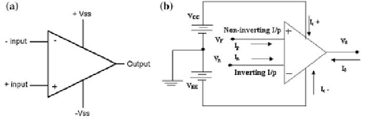
Fig. 7.5
(a) Basic op-amp (b) op-amp circuit
a fixed resistance R
1
of the same value as the nominal value of the unknown
resistance R
u
. As the resistance R
u
changes, the output voltage V
0
varies and this
relationship between V
0
and R
u
must be calculated.
R
u
R
u
þ
R
3
R
1
R
1
þ
R
2
V
0
¼
V
i
The Wheatstone bridge configuration is used in many sensor circuit analysis
technologies and also specifically bridge gas configuration applied in gas sensor
analysis technology.
2. Amplifier for Signal Conditioning Circuit
An amplifier is simply a device that increases the magnitude of voltage, current,
or power. It is the basic building block of Analog Electronic Circuits which is used
in signal conditioning, filtering or to perform mathematical operations. Op-amp is
normally used in closed-loop mode for amplifying and signal conditioning. High
input impedance and low output impedance and high gain differential amplifier is a
basic characteristic of operational amplifier.
The operational amplifier (op-amp) is a voltage controlled voltage source with
very high gain. Op-amp has two input terminals, one output terminal, two power
supply terminals, and a ground connection. The symbol of the op-amp with the
associated terminals and output terminal (ports) is shown in Fig.
7.5
a, b.
Inverting Amplifier
The basic working principle of the inverting amplifier as shown in Fig.
7.6
is
that it simply accepts an input signal referenced to common and amplifies it and
inverts the polarity at the output terminals. The input impedance of the inverting
amplifier is finite. In short the amplifier gives a negative gain to the input voltage,
so output is out of phase with input voltage.
b
¼
R
1
A
0
1
A
0
R
F
R
F
R
1
¼
1
b
R
F
So
;
A
¼
¼
R
1
R
F
1
A
0
R
F
R
1


Search WWH ::

Custom Search