Biomedical Engineering Reference
In-Depth Information
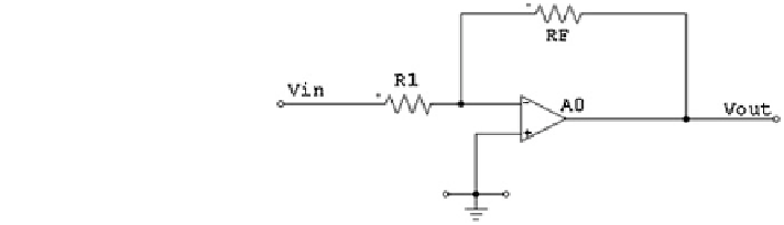
Fig. 7.6
Inverting amplifier
Non-Inverting Amplifier
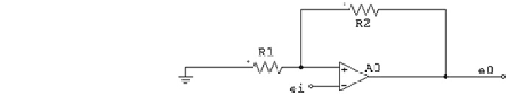
The signal input is applied to the non-inverting (+) input. The inverting input
(-) is grounded. The resistor R
2
is the feedback resistor. It is connected from the
output to the positive (inverting) input. This circuit as shown in Fig.
7.7
can be
used to buffer the output of a sensor from the load effect of the next stage and to
introduce a gain of greater than 1 to the signal. The input impedance of the non-
inverting amplifier is infinite.
e
0
e
i
¼
i
ð
R
2
þ
R
1
Þ
iR
1
¼
R
2
þ
R
1i
R
1
Summing Amplifier (Extension of Inverting)
A common modification of the inverting amplifier is an amplifier as shown in
Fig.
7.8
a, b that sums or adds two or more applied voltages.
R
A
where R
A
¼
V
out
¼
1
þ
R
F
R
a
R
a
V
a
þ
R
A
R
b
V
b
þ
R
A
1
R
c
V
c
R
a
þ
R
b
þ
R
c
1
V
a
þ
V
b
þ
V
c
3
if R
a
¼
R
b
¼
R
c
then V
out
¼
1
þ
R
F
R
B
Differential Amplifier
The inverting and non-inverting properties of an op-amp can be combined
together in a differential amplifier. This circuit as shown in Fig.
7.9
is used to
amplify the difference between two input signals. The two inputs are connected to
Fig. 7.7
Non-inverting
amplifier


Search WWH ::

Custom Search