Graphics Reference
In-Depth Information
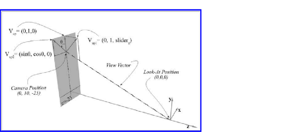
Figure 14.6.
Up vector directions of Tutorial 14.1.
1.
Up vector controls.
The “UpVector Z” slider bar returns slider
z
value, and
the “Twist Angle” slider bar returns
θ
. The up vector is set according to:
up vector
=(
sin
(
θ
)
,
cos
(
θ
)
,
slider
z
)
.
•
UpVector Z.
Notice that this slider bar changes the
z
-component of
the up vector without affecting the
x
-or
y
-components. For example,
as illustrated in Figure 14.6, with
0
◦
, when we change slider
z
,the
θ
=
up vector will be changed to
=(
)
.
V
up
1
0
,
1
,
slider
z
Notice that with default initial camera settings, the rendered image
does not change for different slider
z
values. Here we verify the fol-
lowing.
(a) The up vector does not need to be normalized. As we change the
slider
z
, the size of the up vector also changes, but the rendered
image remains the same.
(b) The up vector does not need to be parallel to the up direction of
the image plane. As we change slider
z
values, the direction of the
up vector changes, and yet the derived image plane up direction
remains the same, and thus the rendered image does not change.
•
Twist angle.
Here we illustrate a simple implementation of the cam-
era twist angle that is defined with respect to the WC
y
-axis.
Fig-


Search WWH ::

Custom Search