Graphics Reference
In-Depth Information
void
CGrfxWindowD3D::OnPaint() {
.
Source file.
GrfxWindowD3D.cpp
file in
the
GrfxWindow
folder of the
D3D
_
AdjustCamera
project.
//
Identical to Listing 13.2
.
Step 2:
initialize selected hardware and set the coordinate system parameters.
// Set
WORLD
matrix processor
.
D3DXMATRIX
matView;
// camera parameters
D3DXVECTOR3
camera
_
pos(...), target
_
pos(...), up
_
vector(...);
// compute
matView
A:
D3DXMatrixLookAtRH(&matView,...camera/target/up
_
vector...);
// load
matView
to D3D VIEW processor
m
_
pD3DDevice->SetTransform( D3DTS
_
VIEW, &matView );
.
// Set
PROJECTION
matrix processor
Listing 14.1.
Details of the
VIEW
matrix processor settings (Tutorial 14.1).
•
Approach.
Re-implement Tutorial 13.1 to support slider-bar control of the
camera parameters. In this way, we can adjust the camera parameters and
examine the resulting image.
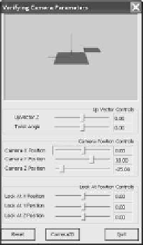
Figure 14.5 is a screenshot of running Tutorial 14.1. The implementation of this
tutorial is modified from that of Tutorial 13.1 to include GUI slider bars that con-
trol the camera parameters. Listing 14.1 shows the programming code for setting
the camera view. In this case, the camera parameter variables—
camera
_
pos
,
target
_
pos
,and
up
_
vector
—are controlled by the corresponding GUI slider
bars. At label A, these parameters are used for the computation of the
matView
matrix, and then the
matView
matrix is loaded into the D3D
VIEW
matrix proces-
sor. The mathematical details of the
matView
matrix will be discussed in Sec-
tion 14.3. Here, we are interested in verifying the effects of the camera parame-
ters. Initially, these parameters are set to those as illustrated in Figure 13.6:
Figure 14.5.
Tutorial
14.1.
camera position
=(
0
,
10
, −
25
)
look-at position
=(
0
,
0
,
0
)
.
up vector
=(
0
,
1
,
0
)
The “Reset” button resets all camera parameters to the above default values. The
following discussion assumes the above camera settings.


Search WWH ::

Custom Search