Graphics Programs Reference
In-Depth Information
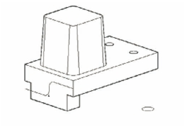
FIGURE 22.10
Hidden-line view
showing parts of
the drawing you'll
use to create a
curved extrusion
The polyline path
The circle you will extrude
3.
At the Select sweep path or [Alignment/Base point/Scale/Twist]: prompt, click
the polyline curve.
4.
AutoCAD generates a solid tube that follows the path. The tube may not look like a tube
because AutoCAD draws extruded solids such as this with four lines showing their profi le.
5.
Click the Subtract tool from the Union fl yout on the Tool Sets palette or type
SU
↵, and
then select the composite solid.
6.
Press ↵. At the Select objects: prompt, click the curved solid you just created and
press ↵. The curved solid is subtracted from the square solid.
7.
Choose View
Hide. Your drawing looks like Figure 22.11.
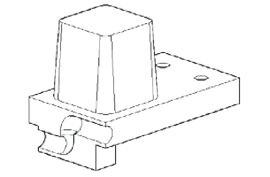
FIGURE 22.11
The solid after sub-
tracting the curve
In this exercise, you used a curved polyline for the extrusion path, but you can use any type
of 2D or 3D polyline, as well as a line or arc, for an extrusion path.