Graphics Programs Reference
In-Depth Information
Creating Complex 3D Surfaces
In the previous example, you drew a chair composed of objects that were mostly straight lines
or curves with a thickness. All the forms in that chair were defined in planes perpendicular to
one another. For a 3D model such as this, you can get by using the orthographic UCSs. At times,
however, you'll want to draw objects that don't fit so easily into perpendicular or parallel planes.
In the following sections, you'll create more-complex forms by using some of AutoCAD's other
3D commands.
Laying Out a 3D Form
In this next group of exercises, you'll draw a butterfly chair. This chair has no perpendicular or
parallel planes to work with, so you'll start by setting up some points that you'll use for refer-
ence only. This is similar in concept to laying out a 2D drawing. As you progress through the
drawing construction, notice how the reference points are established to help create the chair.
You'll also construct some temporary 3D lines to use for reference. These temporary lines will
be your layout. These points will define the major UCSs needed to construct the drawing. The
main point is to show you some of the options for creating and saving UCSs.
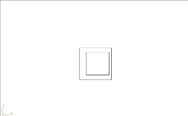
To save time, I've created the 2D drawing that you'll use to build your 3D layout. This draw-
ing consists of two rectangles that are offset by 4˝ (10 mm for metric users). To make it more
interesting, they're also off center from each other (Figure 20.24).
FIGURE 20.24
Setting up a layout
for a butterfly chair
The first thing you'll need to do is set up the drawing for the layout:
1.
Open the butterfly1.dwg file.
2.
Click SW Isometric from the 3D Views menu on the Viewport Controls (Figure 20.25) or
type
V
↵
SWISO
↵. This gives you a view from the lower-left side of the rectangles.