Graphics Programs Reference
In-Depth Information
FIGURE 20.25
The SW Isometric
option in the 3D
View menu
3.
Zoom out so the rectangles occupy about a third of the drawing area window.
Now you need to move the outer rectangle in the Z axis so its elevation is 30˝ (76 cm for
metric users):
1.
Click the outer rectangle, and then click one of its grips.
2.
Right-click to open the Grip Edit shortcut menu.
3.
Choose Move, and then enter
@ 0,0,30↵; metric users should enter
@0,0,76
↵. This tells
AutoCAD to move the rectangle a 0 distance in both the X and Y axes and 30˝ (or 76 cm)
in the Z axis.
4.
Pan your view downward so it looks similar to Figure 20.26.
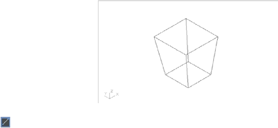
FIGURE 20.26
The fi nished chair
layout
5.
Use the Line tool near the middle of the Tool Sets palette to draw lines from the corners
of the bottom square to the corners of the top square. Use the Endpoint osnap to select the
exact corners of the squares. Your model should look like Figure 20.26. This is the layout
for your chair—not the fi nished product.