Graphics Programs Reference
In-Depth Information
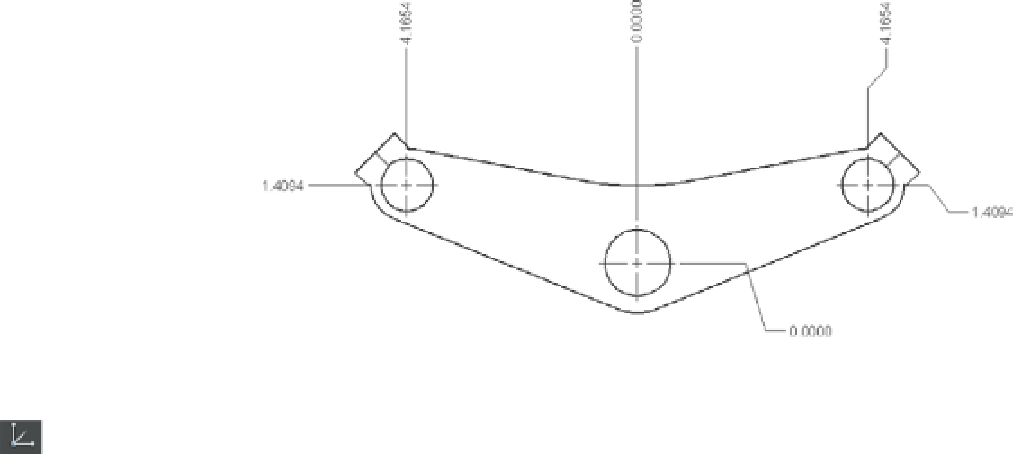
FIGURE 11.35
A drawing using
ordinate dimensions
To use the Dimordinate command, perform the following steps:
1.
On the Drafting tool set of the Tool Sets palette, expand the Coordinates tool group and
click Set UCS Origin, or type
UCS
↵
OR
↵.
2.
At the Specify new origin point <0,0,0>: prompt, click the exact location of the ori-
gin of your part.
3.
Toggle Ortho Mode on in the Status Bar palette.
4.
Choose Dimension
Ordinate on the menu bar. You can also enter
DOR
↵ or click
Ordinate from the Linear Dimension fl yout on the Dimensions tool group to start the
ordinate dimension.
5.
At the Specify feature location: prompt, click the item you want to dimension. The
direction of the leader determines whether the dimension will be of the Xdatum or the
Yd at u m.
6.
At the Specify leader endpoint or [Xdatum/Ydatum/Mtext/Text/Angle]: prompt,
indicate the length and direction of the leader. Do this by positioning the rubber-banding
leader perpendicular to the coordinate direction you want to dimension and then click-
ing that point.
In steps 1 and 2, you used the UCS feature to establish a second origin in the drawing. The
Ordinate tool then uses that origin to determine the ordinate dimensions. You'll get a chance to
work with the UCS feature in Chapter 20, “Using Advanced 3D Features.”
You may have noticed options in the command line for the Ordinate tool. The Xdatum and
Ydatum options force the dimension to be of the X or Y coordinate no matter what direction the
leader takes. The Mtext option displays the in-place text editor and Text Editor visor, enabling
you to append or replace the ordinate dimension text. The Text option lets you enter replace-
ment text directly through the Command prompt.
If you turn off Ortho mode, the dimension leader is drawn with a jog to maintain the orthog-
onal (look back at Figure 11.35).