Graphics Programs Reference
In-Depth Information
The Leaders panel on the Tool Sets palette offers several tools that let you make these types
of changes to your leader notes (refer back to Figure 11.31). The Add Leader and Remove Leader
tools let you add or remove leaders from a multileader. The Add Leader tool is a handy tool if
you want a single note to point to several objects. The Align Leaders tool lets you align the note
portion of several multileaders. Finally, the Collect Leaders tool lets you collect several multi-
leaders that use blocks for notes into a single note.
Breaking a Dimension Line for a Leader
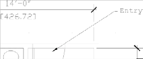
In a crowded drawing, your multileader arrow may have to cross over a dimension line. In
many drafting conventions, when a leader line crosses over a dimension line, the dimension line
must be shown with a gap.
You can apply a gap to a dimension line using the Break Dimension tool. Here's how it works:
1.
Click Dimension Break from the Tool Sets palette.
2.
At the Select dimension to add/remove break or [Multiple]: prompt, select a
dimension line, or enter
M
↵ and select multiple dimension lines.
3.
When you're finished with your selection, press ↵. Note that this ↵ is necessary only
when using the Multiple option.
4.
At the Select object to break dimensions or [Auto/Remove] <Auto>: prompt,
press ↵. A gap appears wherever a leader line or other dimension line crosses over the
selected dimension line.
If you prefer to indicate a break manually, enter
M
↵ at the prompt in step 4. This allows you
to select two points on the dimension, indicating where the gap is to occur. If additional dimen-
sion or leader lines are added that cross over the dimension line, repeat your use of the Break
Dimension tool. To remove an existing break, use the Remove option in step 4 by entering
R
↵.
Applying Ordinate Dimensions
In mechanical drafting,
ordinate dimensions
are used to maintain the accuracy of a machined part
by establishing an origin on the part. All major dimensions are described as X coordinates or Y
coordinates of that origin. The origin is usually an easily locatable feature of the part, such as a
machined bore or two machined surfaces.
Figure 11.35 shows a typical application of ordinate dimensions. In the lower-right corner, note
the two dimensions whose leaders are jogged. Also note the origin location in the center circle.