Environmental Engineering Reference
In-Depth Information
There are several methods for implementing MPP tracker control that will
be described in the following section:
Sensor-controlled regulator
: As described above, the MPP voltage is calculated
as a function of the temperature and irradiance sensor input.
Control using a reference cell
: The characteristics, i.e. open circuit voltage
V
OC
and short circuit current
I
SC
, of a solar cell mounted near the solar generator is
recorded. These measurements allow the estimation of the MPP voltage
V
MPP
.
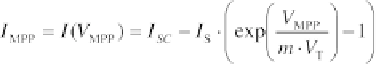
Using the equation of the simple equivalent circuit, the MPP current
I
MPP
becomes:
(4.88)
The derivative of the power with respect to the voltage is equal to zero at the
power maximum:
(4.89)
Inserting
I
MPP
into this equation and solving it for the MPP voltage
V
MPP
results in:
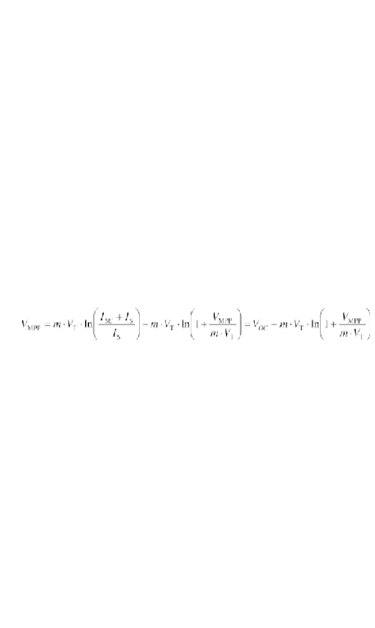
(4.90)
Numerical or approximation methods can be used to solve this equation. The
MPP voltage can be obtained from the open circuit voltage. A more precise
estimate can be made using the two-diode model:
Oscillating search control (hill climbing)
: Voltage and current are measured at
the converter input or output and the power is calculated and stored.
Figure 4.40 shows the principle of this system. Small changes in the duty cycle
cause a voltage change. The power is then estimated again. If the power
increases, the duty cycle is changed again in the same direction. Otherwise, the
duty cycle is changed in the opposite direction. For constant output voltages,
the search for the maximum output current is sufficient. In this case, the power
itself need not to be estimated.
Zero transit method
: Generator voltage and current are measured and
multiplied. A derivative unit estimates the derivative d
P
/d
V
. The generator
voltage is increased or decreased depending whether the derivative is positive
or negative.