Environmental Engineering Reference
In-Depth Information
Generator
Load
Figure 4.39
Flyback Converter Circuit
buck-boost converter, except that the transformation ratio
r
must be
considered. This is defined by the ratio of the number of turns in the winding
on either side of the transformer. Hence, the output voltage becomes:
(4.86)
For high power applications a
push-pull converter
is used that needs more
than one switch. If capacitors replace the inductances, a converter using the
charge pump principle can be realized.
MPP tracker
The above-described voltage converters can maintain different voltages at the
solar generator and at the load. If the solar generator voltage is set to a fixed
value with a chosen duty cycle (see Figure 4.33), the energy yield is much
higher than with a simple resistive load. On the other hand, the optimal
operating voltage varies depending on irradiance and temperature. Therefore,
a variation in the duty cycle of the DC-DC converter changes the solar
generator voltage and thus can improve the energy yield.
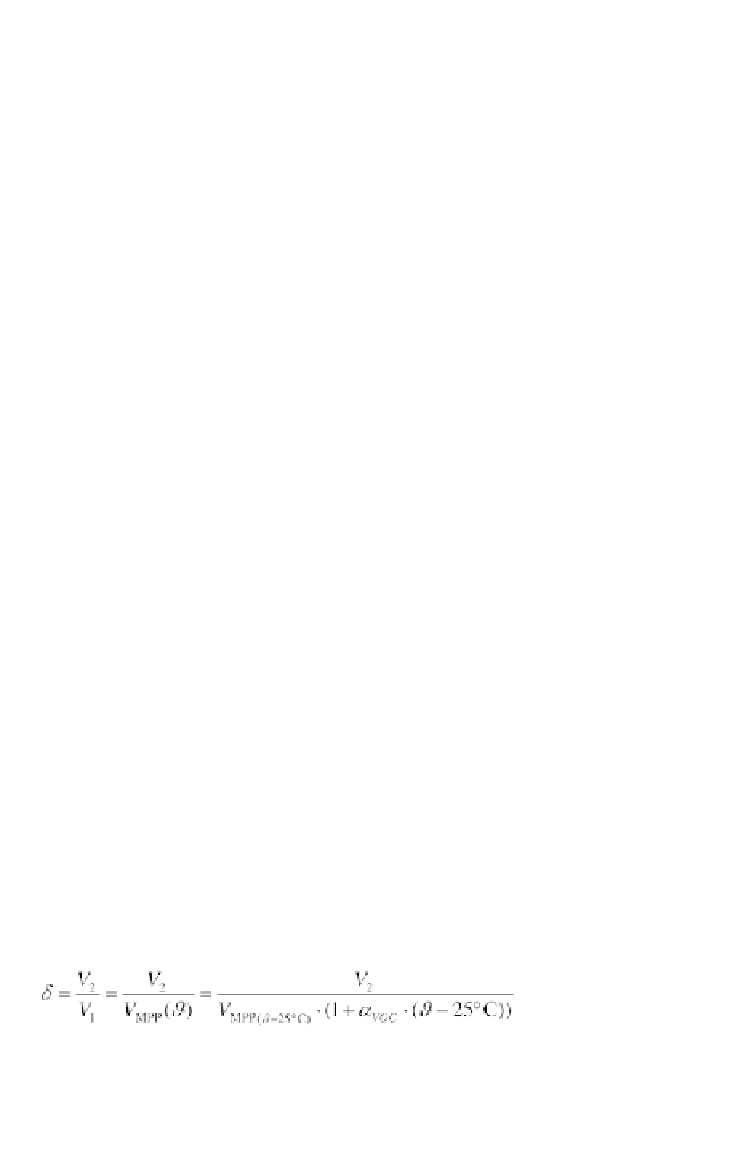
Fluctuations in temperature
have the highest influence on the optimal
solar generator voltage. A temperature sensor attached to the back of a solar
module can measure its temperature. With the temperature coefficient of the
open circuit voltage (e.g.
ϑ
α
VOC
= -3·10
-3
/°C to -5·10
-3
/°C for silicon solar
cells) the duty cycle for a buck converter can be estimated with the MPP
voltage
V
MPP
at a reference temperature and the known output voltage
V
2
:
(4.87)
If the duty cycle additionally is adapted to the solar irradiance, the solar
generator can be operated at the maximum power point in most cases. If the
DC-DC converter operates the solar generator at its MPP, the converter is
called an MPP tracker.