Biomedical Engineering Reference
In-Depth Information
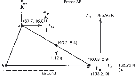
Figure 5.13
Free-body diagram of foot during weight bearing with the ground reaction
forces, F
x
and F
y
, shown as being located at the COP.
5.2.5 Combined Force Plate and Kinematic Data
It is valuable to see how the reaction force data from the force plate are
combined with the segment kinematics to calculate the muscle moments and
reaction forces at the ankle joint during dynamic stance. This is best illustrated
in a sample calculation. For a subject in late stance (see Figure 5.13), during
pushoff the following foot accelerations were recorded:
a
x
3
.
25 m
/
s
2
,
a
y
=
=
1
.
78 m
/
s
2
, and
α
45
.
35 rad
/
s
2
. The mass of the foot is 1.12 kg, and the
moment of inertia is 0
.
01 kg
=−
m
2
.
·
Example 5.4 (see Figure 5.13).
From Equation (5.1),
F
ax
+
F
x
=
ma
x
F
ax
=
1
.
12
×
3
.
25
−
160
.
25
=−
156
.
6N
From Equation (5.2),
F
ay
+
F
y
−
mg
=
ma
y
F
ay
=
1
.
12
×
1
.
78
−
765
.
96
+
1
.
12
×
9
.
81
=−
753
.
0N
=
I α
,
From Equation (5.3), about the center of mass of the foot,
M
M
a
+
F
x
×
0
.
084
+
F
y
×
0
.
079
−
F
ay
×
0
.
056
−
F
ax
×
0
.
076
=
0
.
01
(
−
45
.
35
)
M
a
=−
×
−
×
−
×
−
0
.
01
45
.
35
0
.
084
160
.
25
0
.
079
765
.
96
0
.
056
×
−
×
=−
·
753
.
0
0
.
076
156
.
6
128
.
5N
m


Search WWH ::

Custom Search