Graphics Programs Reference
In-Depth Information
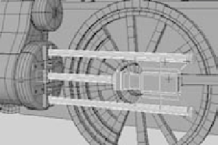
Figure 9.72
Use vertices to extend
the pump arm.
3. To fix the pump arm, select the vertices on
the ends of the cylinders, and extend them to
make them longer, as shown in Figure 9.72.
Now the pump arm won't pull out of the
steam pump assembly.
4. Adjust the pump arm so that the geometry
fits when the pump pushes in as well.
The scene file
fancy_locomotive_anim_v2.mb
will catch you up to this point. Compare it
to your work.
Controlling the Back Wheel
All that remains is to control the animation of the back wheel and its wheel arm. To set
up the wheel arm animation, follow these steps:
1. Using the methods described in the steps in the “Controlling the Wheel Arms” sec-
tion, create a joint to follow along the wheel arm between the middle control wheel
and the back wheel. The root of the joint is set at the control wheel, as shown in
Figure 9.73.
Figure 9.73
Create a joint to
control the back
wheel arm.
2. As before, create an IK handle for the end joint of this new bone, where it meets the
back wheel, as shown in Figure 9.74. Make sure the handle is at the back wheel, not
the middle control wheel.
3. Group the new joint under the master wheel, and then group the wheel arm under
this new joint. If you rotate the control wheel, the wheel arm rotates with the joint
and wheel but doesn't connect to the back wheel yet. You need to attach the IK handle
you just created for that joint to the back wheel.