Graphics Programs Reference
In-Depth Information
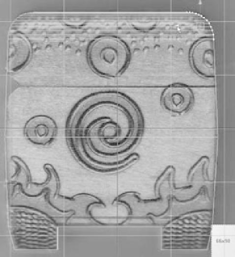
13. Use the new vertices to bow out the box in the middle slightly. Adjust the rest of
the vertices to match the model to the box images in the side and front views.
(See Figure 6.154.)
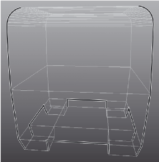
14. Now bevel the edges of the box throughout, to soften the crisp corners of the
cube that the real box doesn't have. Select all the outer edges of the cube shown
in Figure 6.155.
Pick these edges
Figure 6.154
Adjust the cube to fit the box images.
Figure 6.155
Select these edges for beveling.
15. Select the reference images, and hide them by selecting Display
➔
Hide
➔
Hide Selec-
tion or by pressing Ctrl+H. You can unhide them by selecting them again in the
Outliner and selecting Display
➔
Show
➔
Show Selection or by pressing Shift+H.
Notice that when an object is hidden, its Outliner entry is grayed out.
16. With those edges selected, select Edit Mesh
➔
Bevel
r
. Set everything to the defaults,
but change Segments from 1 to
3
. Click Bevel, and your box should resemble the one
shown in Figure 6.156.
17. Select the cube, and delete its history by selecting Edit
➔
Delete by Type
➔
History.
Save your work.
18. You have one final detail to tend to on the lid. You need to add the hinge area you
can see in the Side view panel's reference image. Select the reference planes in the
Outliner (pPlane1, pPlane2, and pPlane3), and press Shift+H to unhide them. Make
sure you're in Textured mode in your views (press 6).