Graphics Programs Reference
In-Depth Information
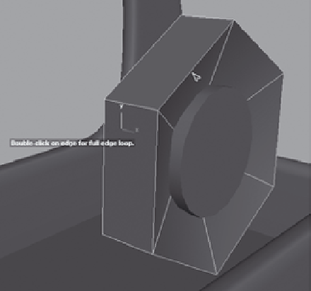
Figure 6.86
Select the outer
loop of edges.
Select the outer
ring of edges
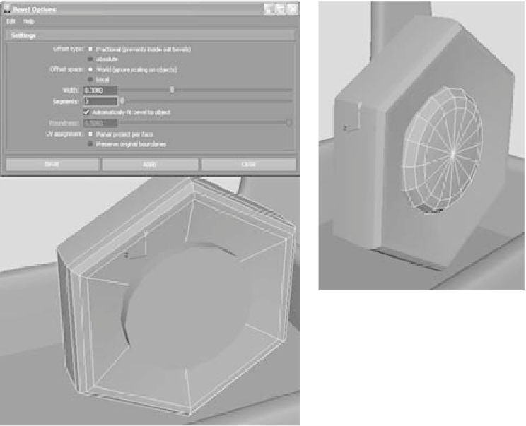
6. Bevel the outer loop of edges with a Width setting of 0.3 and a Segments value of 3,
as shown in Figure 6.87.
7. Select the outer loop of edges for the inner cylinder, and bevel them with the same
settings. Figure 6.88 shows the result.
Figure 6.87
Bevel the end of
the bolt head.
Figure 6.88
Bevel the inner cylinder.