Graphics Programs Reference
In-Depth Information
R50
R10
50
Fig. 17.22
Second example - 2D outlines in 3D space. Outline to be extruded
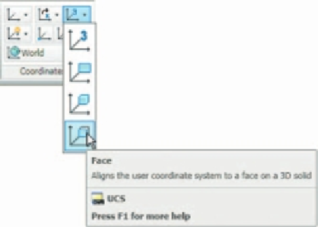
4.
Click
the
Face
tool icon in the
View/Coordinates
panel ( Fig. 17.23 )
and place the 3D model in the ucs plane shown in Fig. 17.24, selecting
the sloping face of the extrusion for the plane and again
Zoom
to
1
.
5.
With the
Circle
tool draw fi ve circles as shown in Fig. 17.24.
6.
Form a region from the fi ve circles and with
Union
form a union of the
regions.
7.
Extrude the region to a height of −
60
(note the minus) - higher than the
width of the sloping part of the 3D model.
8.
Place the model in the
ViewCube/Isometric
view and subtract the
extruded region from the model.
9.
With the
Fillet
tool, fi llet the upper corners of the slope of the main
extrusion to a radius of
30
.
Fig. 17.23
The Face icon from the View/Coordinates panel


Search WWH ::

Custom Search