Graphics Programs Reference
In-Depth Information
axis
R50
Hole Ø80
5
Ø140
R15
Ø110
Holes Ø10
R15
R10
30
40
Fig. 14.8
Example
of constructing a 3D
model - outline for
solid of revolution
Ø90
Hole Ø50
Ø60
R15
Fig. 14.7
Orthographic drawing for the example of constructing a 3D model
3.
Set the
View/Views/Top
view and with the
Cylinder
tool, construct
cylinders as follows:
In the centre of the solid - radius
50
and height
50
.
With the same centre - radius
40
and height
40
. Subtract this cylinder
from that of radius
50
.
At the correct centre - radius
10
and height
25
.
At the same centre - radius
5
and height
25
. Subtract this cylinder
from that of radius
10
.
4.
With the
Array
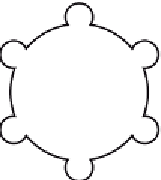
tool, form a polar
6
times array of the last two
cylinders based on the centre of the 3D model.
5.
Set the
View/Views/Front
view.
6.
With the
Move
tool, move the array and the other two cylinders to
their correct positions relative to the solid of revolution so far
formed.
7.
With the
Union
tool form a union of the array and other two
solids.
8.
Set the
View/Views/Right
view.
9.
Construct a cylinder of radius
30
and height
25
and another of radius
25
and height
60
central to the lower part of the 3D solid so far
formed.
10.
Set the
View/Views/Top
view and with the
Move
tool move the two
cylinders into their correct position.


Search WWH ::

Custom Search