Graphics Programs Reference
In-Depth Information
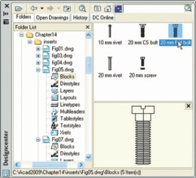
bolt and a hexagonal head bolt together with its nut (Fig. 14.5). With the
Create
tool save each separately as a block, erase the original drawings
and save the fi le to a suitable fi le name - in this example Fig05.dwg.
2.
Open the DesignCenter,
click
on the
Chapter 14
directory, followed
by a
click
on
Fig05.dwg
. Then
click
again on
Blocks
in the content list
of
Fig05.dwg
. The fi ve 3D models of fastenings appear as icons in the
right-hand side of the DesignCenter (Fig. 14.6).
3.
Such blocks of 3D models can be
dragged
and
dropped
into position in
any engineering drawing where the fastenings are to be included.
Fig. 14.5
Second
example - the fi ve
fastenings
Fig. 14.6
Second example - a library of fastenings
Constructing a 3D model ( Fig. 14.9 )
A three-view projection of a pressure head is shown in Fig. 14.7. To
construct a 3D model of the head:
1.
Select
Front
from the
View/Views
panel.
2.
Construct the outline to be formed into a solid of revolution (Fig. 14.8)
on a layer colour magenta and with the
Revolve
tool, produce the 3D
model of the outline.


Search WWH ::

Custom Search