Hardware Reference
In-Depth Information
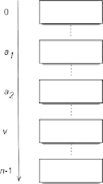
Fig. 6.13
Example of linked
fault
different aggressor cells with addresses a
1
and a
2
, the same victim cell with ad-
dress
v
,anda
1
<a
2
<
v
. According to FP
1
, starting with a
1
equal to 0 and by
performing
w
a
1
1
, the victim cell
v
flips from 0 to 1; then, starting with a
2
equal to
0 and performing
w
a
2
1
, according to FP
2
the victim cell
v
changes its value again,
from 1 to 0. The global result is that the fault effect is masked by the application of
FP
2
,sinceFP
2
has a faulty behavior opposite to FP
1
.
Basedonthisexample,twoFPs,
FP
1
D
<
SOS
1
=
FB
1
>,and
FP
2
D
<
SOS
2
=
FB
2
> are linked, and denoted by
FP
1
!
FP
2
, if both of the follow-
ing conditions are satisfied:
FP
1
masks FP
2
, i.e.,
FB
2
!
FB
1
.
SOS
2
is applied after SOS
1
, on either the aggressor cell or the victim cell of FP
1
.
To detect linked faults (LFs), it is necessary to detect in isolation at least one of
the FPs that compose the fault (i.e., preventing the other FP to mask the fault)
(
Hamdioui et al.
2004
).
Among the extended space of possible linked FFMs, based on several simulations
on defective memory devices, the following established realistic linked FFMs have
been defined (
Hamdioui et al.
2004
):
Single cell linked faults
: involve a single memory location where all FPs are
sequentially applied. Table
6.3
reports the list of realistic single-cell linked faults.
2-coupling linked faults
: 2-coupling linked faults involve two distinct memory
cells: one aggressor cell a, and one victim cell
v
. Two different situations may
happen: (i) a<
v
, and (ii)
v
<a. Based on this distinction realistic 2-coupling
linked faults can be clustered in three different classes: (i) linked faults based on
a combination of 2-coupling FPs that share both the aggressor and the victim cell
.LF2
aa
/, (ii) linked faults where FP
1
is a 2-coupling FP and FP
2
is a single-cell
FP .LF2
av
/, and (iii) linked faults where FP
1
is a single-cell FP and FP
2
is a