Geology Reference
In-Depth Information
C
Himalayan Fold
n
d
FBF
Model
D
FBF Landscape
st
A
Main Frontal Thrust
1000
Aligned Valleys
Aligned
Valley
800
600
a
400
200
0
fault-bend
fold (x-section)
5
Distance (km)
10
B
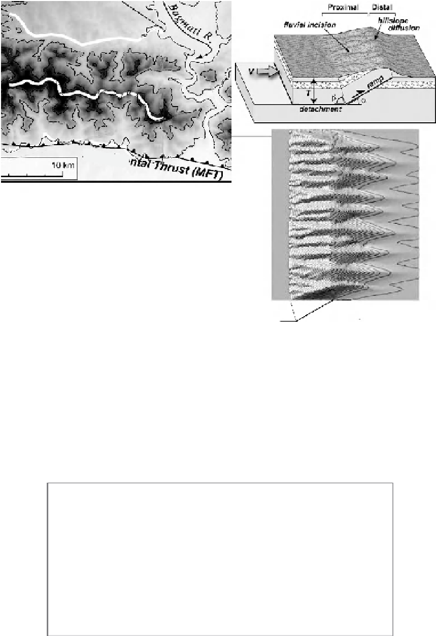
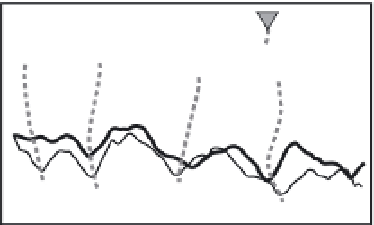
Fig. 9.28
Topographic advection on fault-bend folds.
A. Contour map of topography on a fault-bend fold developed above the Main Frontal Thrust in central Nepal (see
Fig. 8.21 for cross-section). Lines along the crest and the distal and proximal flanks depict the location of topographic
profiles in B. B. Topographic profiles show an overall alignment of major valleys on both fold flanks and the ridge
crest. C. Set-up for numerical model of eroding topography above a rapidly advecting fault-bend fold (FBF). D. Map
view of predicted model topography depicting clear valley alignment on either flank of the fold. Cross-section at
bottom shows relationship of kinks in the fault surface to the topography. Modified after Miller and Slingerland (2006)
and Miller
et al.
(2007).
A
B
age of uplifted surface
uniform age of
each uplifted surface
old
young
T1
T3
T3
T2
T2
T2
T1
T3
T1
Fixed Tip with
Fold Amplification
T1
T2
T3
Propagating Tip
Fig. 9.29
Propagating versus fixed-tip folds.
A. Propagating fold tip in which the geomorphic surface beyond the fold tip is progressively incorporated into the
propagating tip, causing surface ages to get younger toward the tip. T1 to T3 represent both time increments of fold
growth and surface ages along the fold's crest. B. Fixed-tip fold in which continued displacement leads to
amplification of the fold. The upper surface has the same age, irrespective of position with respect to the tip.