Civil Engineering Reference
In-Depth Information
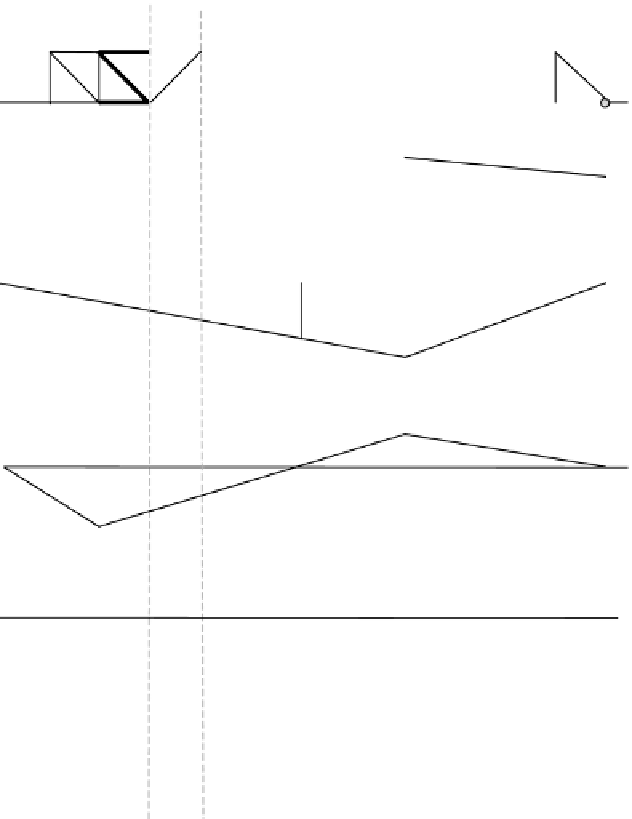
Symmetrical
about center line
U2
U3
15'
30'
L2
L3
L0
L6
12 @ 25' = 300'
0.33
Reaction at L0
1.00
1.00
Reaction at L6
1.33
0.56
Axial force L2-L3
1.11
1.11
0.74
Axial force U2-U3
0.43
0.43
0.65
Axial force U2-L3
FIGURE E5.9
5.2.1.3
Equivalent Uniform Loads for Maximum Shear Force and
Bending Moment in Simply Supported Spans
The methods outlined in Sections 5.2.1.1 and 5.2.1.2 require iteration that can be
readily computerized. However, for concentrated design loads used on many bridge
spans (e.g., Cooper's configuration) it is often beneficial to determine an equivalent
uniform load,
w
e
, that represents the effects of the concentrated design loading.
∗
∗
Equivalent uniform loads are particularly useful for preliminary design.