Civil Engineering Reference
In-Depth Information
S
d'
P
h
Concrete slab
d
Longitudinal distribution to transverse members
§ Track
5
'
Tie
P
/2
P
/2
d'
h
Transverse floorbeam
5
'
a
Lateral distribution to transverse members
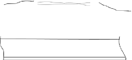
FIGURE 4.18
Longitudinal and lateral distribution of live load on ballasted deck bridges
with transverse floorbeams.
where
d
is the transverse beam spacing
≤
S
,ft(if
d > S
then assume the with deck
as simply supported between transverse beams). In the previous equation,
a
is the
transverse beam span, ft,
H
is given by
nI
b
ah
3
in.
/
ft,
H
=
n
is the steel to concrete modular ratio,
I
b
is the transverse beam moment of inertia,
in.
4
, and
h
is the concrete slab thickness, in. No lateral distribution of load is made
for transverse beams supporting ballasted decks (Figure 4.18).
Example 4.11
The longitudinal distribution of Cooper's E80 axle loads to 16 ft long trans-
verse
W
36
×
150floorbeamsspacedat2.5 ftsupportinga7 in.thickreinforced