Information Technology Reference
In-Depth Information
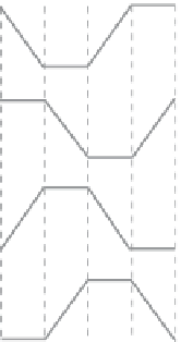
Clock zone 0
Clock zone 1
Clock zone 2
Clock zone 3
Figure
4.7.
The four phases of the QCA clock used to control information flow in
the QCA circuit.
A length of QCA wire can be represented schematically, as shown in Figure 4.8,
where each clock zone is identified in the layout with a unique shade of gray. This
deep (or fine-grained) pipelining has a major effect on the design cost function.
Schematics of QCA circuits should include these D-latches to represent the
clocking zones, as also shown in Figure 4.8.
The deep pipeline inherent in QCA circuits forces us to evaluate our designs
differently than we would if we were designing with traditional technologies. Even
in heavily pipelined transistor based logic architectures, there will normally be
many gates in a combinational structure between each latch in the pipeline. In
QCA, the latency is determined completely by the largest number of clocking
zones between input and output, with each gate and wire connection being
connected to a clocking zone. The original concept of QCA, as a quantum level
implementation of classical cellular automata (CA) [2],
is evident from the
Information flow
In
Out
C0
C1
C2
C3
C0
C1
C2
C3
D0
D1
D2
D3
D0
D1
D2
D3
Out
In
Figure
4.8.
QCA wire shown with cells and schematic representation. C0, C1, C2,
C3 are the four phases of the clock. Each of the clocking zones maps to a
numbered D-latch in the circuit representation and is represented in the layout
with a unique shade of grey. Notice that only one clocking zone is latched.


Search WWH ::

Custom Search