Environmental Engineering Reference
In-Depth Information
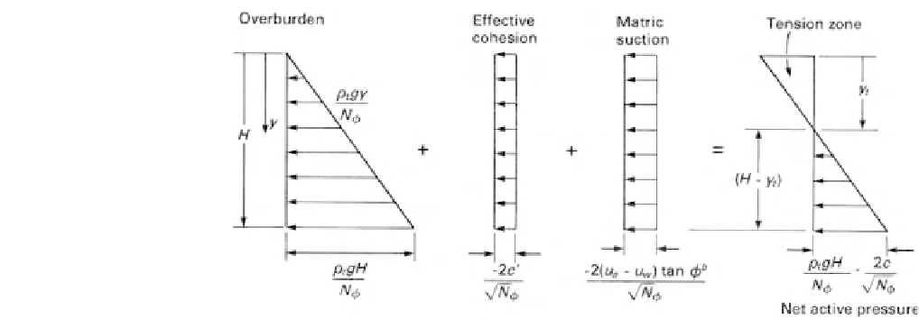
Figure 12.41
Components of active earth pressure distribution when matric suction is constant
with depth.
Figure 12.43
Designation of equilibrium matric suction profile.
12.3.8 Active Earth Pressure Distribution
with Tension Cracks
The soil behind a retaining wall often has tension cracks. It
should be noted that the depth of tension cracks in the soil
must be considered as being analytically independent from
the tension zone depth against the retaining wall. The depth
of cracking is given the variable
y
c
, and the soil above this
depth can be considered as a surcharge load applied to the
underlying soil (Fig. 12.45). Equation 12.46 applies to the
case under consideration as long as the water table is below
the bottom of the tension cracks.
The surcharge load
q
s
must be applied below a depth
y
c
and is equal to the overburden pressure (i.e.,
q
s
=
Figure 12.42
Matric suction causes soil to pull away from retain-
ing wall.
The active pressure
p
a
at any depth above the water
table is
D
(12.47)
The active pressure distribution diagram along with the
plot of each of the components is shown in Fig. 12.44.
The tension zone depth
y
t
can be computed by setting the
total horizontal stress to zero and assuming an atmospheric
air pressure (i.e.,
u
a
=
1
2
c
N
φ
−
u
w
)
h
tan
φ
b
N
φ
1
N
φ
−
2
(u
a
−
y
p
a
=
(σ
v
−
u
a
)
−
ρgy
c
). An
appropriate total density
ρ
must be used for the upper soil
with the tension cracks. The active pressure above the water
table can be derived in a manner similar to the previous
cases. The active pressure at any depth can be written as
0) in Eq. 12.41:
2
c
N
φ
+
u
w
)
h
tan
φ
b
N
φ
2
N
φ
2
(u
a
−
y
t
=
ρg
2
c
N
φ
σ
v
−
u
a
p
a
=
−
2
N
φ
D
N
φ
u
w
)
h
tan
φ
b
+
(u
a
−
(12.48)
1
u
w
)
h
tan
φ
b
N
φ
2
(u
a
−
y
q
s
N
φ
−
−
+
(12.49)
D
−
y
c
where
y
t
<D
.


Search WWH ::

Custom Search