Environmental Engineering Reference
In-Depth Information
12.3.4 Coefficient of Active Earth Pressure
Let us define the coefficient of active earth pressure as
the ratio of the net horizontal pressure to the net vertical
pressure:
assuming an atmospheric air pressure (i.e.,
u
a
=
0) in Eq.
12.40 or 12.41:
ρg
N
φ
+
N
φ
2
c
u
w
)
tan
φ
b
ρg
2
(u
a
−
y
t
=
(12.44)
σ
h
−
u
a
K
a
=
(12.42)
The tension zone depth
y
t
is equal to the depth of the vertical
cracking,
y
c
, when the tensile strength of the soil is assumed to
be negligible. The tension zone depth increases as the matric
suction of the soil increases. This depth corresponds to the
zone which would pull away from the wall as the wall moved
horizontally away from the soil. Figure 12.42 illustrates how
matric suction causes a soil to pull away from the wall.
σ
v
−
u
a
Normalizing the net horizontal stress by the vertical stress
allows the coefficient of active earth pressure to be written
as follows:
2
c
σ
v
−
1
N
φ
−
1
N
φ
−
2
u
a
−
u
w
1
N
φ
(12.43)
tan
φ
b
K
a
=
u
a
σ
v
−
u
a
12.3.7 Active Earth Pressure Distribution (Linear
Decrease in Suction to Water Table)
Let us assume that the matric suction in the soil decreases
linearly with depth to a value of zero at the water table
(Fig. 12.43). The negative pore-water pressure at ground sur-
face for hydrostatic conditions can be written as a function
of the distance from the groundwater table:
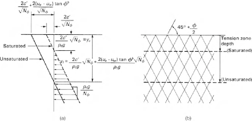
12.3.5 Active Earth Pressure Distribution (Constant
Suction with Depth)
The horizontal pressure corresponding to the active state
can be computed for various depths and plotted as shown in
Fig. 12.40a. Conjugate planes are formed in the soil mass at
angles of 45
φ
/
2 to the horizontal, as shown in Fig. 12.40b
for the active case. The earth pressures for the saturated soil
are designated using effective cohesion
c
and effective angle
of internal friction
φ
. Let us suppose that matric suctions
were a constant value with depth. Then the total cohesion is
also a constant with respect to depth, and the active pressure
distribution is translated to the left, parallel to the saturated
soil case. Figure 12.41 shows the breakdown of the active
pressure into its three stress distribution components.
+
(u
a
−
u
w
)
h
=
ρ
w
gD
(12.45)
where:
(u
a
−
u
w
)
h
=
matric suction at ground surface and
D
=
depth from ground surface to the water
table.
A simple relationship can be used to define the variation in
matric suction with depth for this profile. For depth
y
≤
D
,
12.3.6 Tension Zone Depth
The tension zone depth
y
against the wall can be com-
puted by setting the total horizontal pressure to zero and
the matric suction can be written as
u
w
)
h
1
D
y
(u
a
−
u
w
)
y
=
(u
a
−
−
(12.46)
Figure 12.40
Rankine active earth pressure distribution for saturated soil and soil with constant
matric suction with depth: (a) active pressure distribution corresponding to active pressure case;


Search WWH ::

Custom Search