Hardware Reference
In-Depth Information
•
The MCU sends one or multiple bytes of data to the DS1307 and the DS1307
acknowledges each byte received.
•
The MCU generates the stop condition to terminate the data write.
S
LAVE
T
RANSMITTER
M
ODE
In this mode, the MCU sends the device address of the DS1307 and the address of the reg-
ister to be read to the DS1307, and reads back one or multiple data bytes from the DS1307. The
following events occur:
•
The MCU generates a start condition.
•
The MCU sends a device address byte to the DS1307 with the direction bit (R/W)
set to 0.
•
DS1307 acknowledges the address byte.
•
The MCU sends the address of the register to be accessed to the DS1307. This
value sets the register pointer. The register pointer is incremented by 1 after each
register transfer.
•
The DS1307 acknowledges the register address byte.
•
The MCU generates a restart condition.
•
The MCU sends the device address to the DS1307 with the direction bit set to 1.
•
The DS1307 acknowledges the device address byte.
•
The DS1307 sends one or multiple bytes to the MCU, and the MCU acknowledges
each byte received except the last byte.
•
The MCU generates the stop condition to terminate the data read.
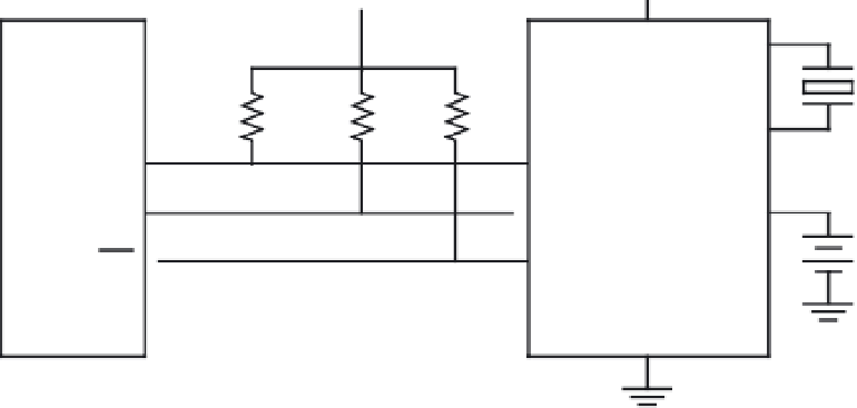
The circuit connection between the DS1307 and the HCS12 is shown in Figure 11.30.
The HCS12 may also connect an LCD or LED circuit to display the current time and calendar.
5 V
5 V
5 V
8
1
HCS12
V
CC
32.768
kHz
2
2.2 k
Ω
2.2 k
Ω
2.2 k
Ω
DS1307
5
SDA
SDA
6
3
SCL
SCL
7
3 V
IRQ
SQWOUT
5V
PJO
GND
100
2.2 k
Ω
4
Figure 11.30
■
Typical circuit connection between the HCS12 and the DS1307


Search WWH ::

Custom Search