Hardware Reference
In-Depth Information
Bit 7
Bit 0
CH
10 seconds
Seconds
10 minutes
Minutes
0
10 HR
A/P
12
24
0
10 HR
Hours
0
0
0
0
0
Day
Date
0
0
10 date
10
month
Month
0
0
0
10 year
Year
OUT
0
0
SQWE
0
0
RS1
RS0
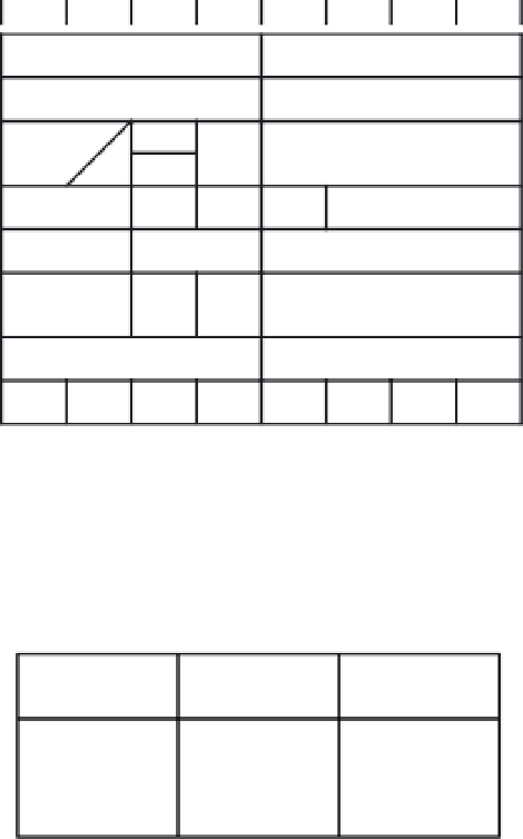
Figure 11.29
■
Contents of RTC registers
The frequency of the square wave output is set by programming the RS1 and RS0 bits with
appropriate values. Table 11.7 lists the square wave frequencies that can be selected with the
RS bits.
SQW Output
Frequency
RS1
RS0
0
0
1
1
0
1
0
1
1 Hz
4.096 kHz
8.192 kHz
32.768 kHz
Table 11.7
■
Square wave output frequency
The DS1307 supports the standard mode (100 kbps baud rate) of the I
2
C bus. The device ad-
dress of the DS1307 is %1101000. There are two types of data transfer between the DS1307 and
an MCU:
slave receiver mode
and
slave transmitter mode
.
S
LAVE
R
ECEIVER
M
ODE
In this mode, the MCU sends the device address of the DS1307, the address of the register
to be accessed, and one or multiple data bytes to the DS1307. The following events occur:
•
The MCU generates a start condition.
•
The MCU sends a device address byte to the DS1307 with the direction bit (R/W)
set to 0.
•
DS1307 acknowledges the address byte.
•
The MCU sends the address of the register to be accessed to the DS1307. This
value sets the register pointer. Only the address of the first register needs to be sent
to the DS1307 during a multiple-byte transfer.
Search WWH ::

Custom Search