Graphics Reference
In-Depth Information
●
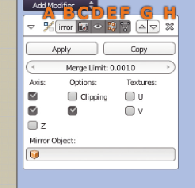
F—Direct Edit: This option has slightly different effects
depending on which modifier you're using. Generally,
it lets you treat any geometry generated by the modifier
as though it were real, live geometry in Edit mode.
For example, enabling Direct Edit on the current
example will let you select vertices in either the “origi-
nal” circle or in the “copy.”
●
G—Up/Down: Raises or lowers the modifier, if there
are more than one. Modifiers are calculated and applied
from the top down, and the results aren't always the
same if you change the order.
●
H—Delete.
In addition to those controls, each modifier has it's own set
of buttons. In the case of the Mirror modifier, we are con-
cerned with the axes buttons along the left. As a default,
x
is checked, which means that the
mesh will mirror along the object's
local
x
axis.
Figure 4.31
The Mirror modifier panel.
LMB click the
y
axis button. You
now have four versions of the
circle, mirrored along two differ-
ent axes. Moving the original
around in Edit mode becomes
kind of funkadelic.
So what good is this? Well, we're
trying to make a shape like the
one in
Figure 4.32
. Just four
circles slightly intertwined. Sure,
you could have created several
duplicates of the circle and posi-
tioned them this way, but using
the modifier and positioning all
four intertwined like this is much
more intuitive and faster.
Select and delete the vertices
within the areas of intersection—
you won't need them. We're going to extrude this whole form downward. Making sure that all the vertices
are selected, switch to a side or front view and use the E key to extrude (constrain for downward motion
with the Z key).
Figure 4.32
Four circles joined, extruded, and loop cut.

Search WWH ::

Custom Search