Biomedical Engineering Reference
In-Depth Information
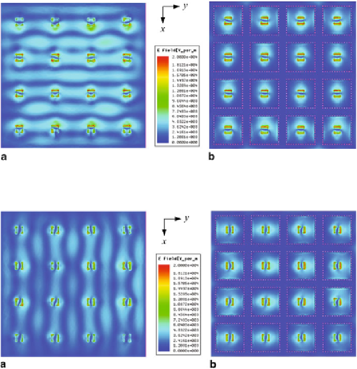
Fig. 29
Simulated electric field distributions on the
top
substrate surface of two cases arrays for
Port H.
a
Without the open-ended SICs structure,
b
With the open-ended SICs structure
Fig. 30
Simulated electric field distributions on the
top
substrate surface of two cases arrays for
Port V.
a
Without the open-ended SICs structure,
b
With the open-ended SICs structure
Similarly, for Port V exciting, strong electric field from the surface waves existing
in the area between the antenna elements in Fig.
30
a, in particular along the
x
-axis,
disturb the original phase of each element. For this reason, the radiation performances
of antenna array are deteriorated. After employing the open-ended SICs structure,
as Fig.
30
b shows, the surface wave is substantially suppressed to result in the gain
enhancement of the antenna array.
Simulated and Measured Results
Figure
31
shows the photograph of the fabricated antenna array with the open-ended
SICs and two GCPW-SL transitions.
Search WWH ::

Custom Search