Biomedical Engineering Reference
In-Depth Information
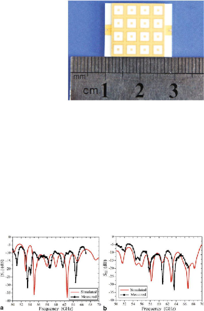
Fig. 31
Photograph of the
proposed fabricated
dual-polarized antenna array
with open-end SICs
The measured and simulated
S
parameters of the proposed antenna array are
illustrated in Fig.
32
. The simulated 10-dB impedance bandwidths are
∼
19.1 %
with respect to 60.25 GHz from 54.5 to 66 GHz for Port H, and
24.4 % with
respect to 61.5 GHz from 54 to 69 GHz for Port V, respectively. The measured
reflection coefficients of antenna array is slightly worse than the simulated values.
The discrepancy could come from the LTCC fabrication tolerance and substrate
shrink, the inaccuracy of the dielectric permittivity, and even from the touching
position of the Ground-Signal-Ground (GSG) probe influence.
Figure
33
shows the measured and simulated input ports isolation of the proposed
dual-polarized antenna array. It can be seen that, the simulated |
S
21
| of the antenna
array is less than
∼
−
25 dB from 58.5 to 65 GHz. Whereas, the measured isolation
|
S
21
| is below
20 dB over the frequency range from 58.5 to 65 GHz.
The measured gain of the proposed antenna array for Port H and Port V are plotted
in Fig.
34
, and compared with the simulated results. Considering the metal chuck and
the different calibrations needed for this setup (standard horn antenna, waveguide
−
Fig. 32
Measured and simulated
S
parameters of the antenna array,
a
Port H (|
S
11
|),
b
Port V (|
S
22
|)
Search WWH ::

Custom Search