Biomedical Engineering Reference
In-Depth Information
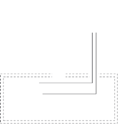
Computer
with A/D converter
BioAmplifier
Head stage
Instron control tower
F
FIGURE 9.10
Setup of the test system.
(BMA-931, CWE Inc., United States) via an ultrahigh-input impedance (over
10
12
Ω) head stage (Super Z, CWE Inc., United States), whose input impedance
was at least two orders higher than that of bone and was able to prevent the
charges accumulated on the electrodes from leaking through the head stage.
In the measurement, the amplified voltage signals were recorded by a com-
puter. Loads were applied using an Instron 1343 closed-loop servo-hydraulic
machine controlled by an 8800 Control Tower, and the loading signals in the
control tower were also input into the computer for recording.
The testing sample and the head stage were enclosed in a double elec-
tromagnetic shield box with the outer shield connecting to ground and the
inner to the head stage common terminal. This arrangement kept the electric
field distribution constant in the device [31].
9.4.3 Experimental Procedure and Characteristics of Piezovoltage
Figure 9.11 shows a trapezoidal loading configuration applying to the sam-
ples in the experiment reported in Hou et al. [4]. It has equal loading and
unloading time
t
o
.
(These researchers employed
t
o
= 0.25, 0.5, and 1 s.) Having
reached its maximum
F
o
(
F
o
= 50, 100, and 150 N in the experiment), the
load was kept constant for 6 s and then decreased to zero (see Figure 9.11a).
Hou et al. noted that the cortical bone had weak viscoelasticity, especially
dry bone [32]. To reduce the effect of viscoelasticity, the maximum compres-
sive stresses in the samples, caused by the maximum
F
o
,
were between 12 and
23 MPa, which was much less than 80 Mpa, below which no irrecoverable