Biomedical Engineering Reference
In-Depth Information
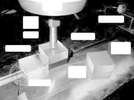
Shaker
Electronics
Load
Cell
Probe
Top Plate
Friction
Surface
PVDF Film
Bottom
Plate
Electrode
Figure 3.21
In this part of the experimental setup the PVDF film is sandwiched between two
plates. The internal surfaces of the plates are covered with the pre-characterized surfaces
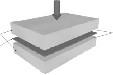
F
N
Contact
surfaces
Plexiglass
PVDF film
Figure 3.22
The configuration used for the experiment to measure the PVDF response to the
friction material
To apply a repetitive load, a signal generator with sinusoidal output was used. Before
connecting this signal to the shaker, the signals were amplified using a power amplifier
(V203, PA25E-CE; Ling Dynamic Systems).
To characterize the output voltage of the PVDF films sandwiched between the two
surfaces, a calibrated load sensor (Kistler 9712B50) was used to record the amplitude of
the applied load. To record and analyze the output of the PVDF film when the friction
coefficient of the surfaces was changed, a data acquisition system (National Instrument,
NI PCI-6225) running LabVIEW software was used. To connect the piezoelectric charge
output to the DAQ, a charge amplifier was used in which an operational amplifier converts
the charge into voltage. In contrast to the voltage-mode amplifiers in which the output
voltage depends on the input impedance, the output voltage in charge-mode amplifiers
depends on the feedback capacitor,
C
f
and the charge developed on the piezoelectric
film,
Q
. Therefore, the output voltage of the charge amplifier is independent of the cable
capacitance. This is one of the main advantages of using charge amplifiers in piezoelectric
applications. The voltage gain can be determined by the ratio
Q/Cf
. Using a LabVIEW