Biomedical Engineering Reference
In-Depth Information
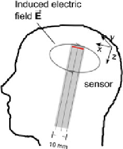
Fig. 2.1 Idea of end-to-end
accuracy measurement for
TMS: When using a sensor
inside a head model, the
induced electric field can be
measured like in a real TMS
setting. The sensor measures
the electric field in the x/y-
plane (denoted by the bold
line on top of the sensor for
the x-directed electric field)
of a 3
3 rotational part, including the rotation angles, and a translational part
representing the three-dimensional position.
As real head motion is now available in robot coordinates, we can mount the
field sensor—embedded in the head phantom—to a robot R
1
to mimic the recorded
head motion. The field sensor will exactly retrace the recorded head motion to
simulate real TMS scenarios. For stimulation, we use a second robot R
2
placed
next to the first robot R
1
and mount the TMS coil to R
2
(Fig.
2.3
). We calibrate R
2
to the tracking system and attach a marker to the head phantom. We can now use
the second robot to actively compensate for the residual head motion measured
with the marker. While we replay the head motion, we measure the induced
electric field produced by the TMS coil with the field sensor.
Even though we have the head motion recorded in robot coordinates, we cannot
directly use the recorded marker poses as targets for the robot's end effector: First,
the head marker position is partially not in the robot workspace as it is attached to
the subject's forehead. And second, we have recorded the position and orientation
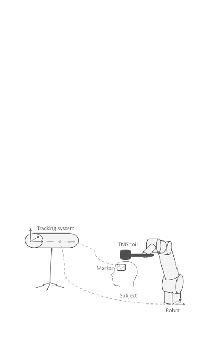
Fig. 2.2 The main principle of motion recording. With a marker at the subject's head we
measure head motion with a tracking system. Using a calibration from tracking system to robot,
we can record the motion in robot coordinates
Search WWH ::

Custom Search