Biomedical Engineering Reference
In-Depth Information
(a)
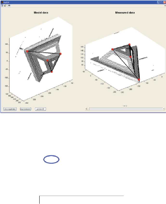
Graphical user interface for landmark and ICP registration. Manually placed landmarks are shown with red spheres.
The left image is the
mode limage
, which is transformed to match the right image .
(the data image)
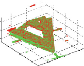
Landmark−based registration
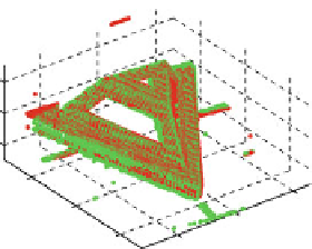
ICP−based registration
150
150
100
100
50
50
0
0
0
0
−100
−100
−100
−100
−200
−200
−200
−200
target surface
model surface
(b)
Results of the registration process. The left figure shows the output of the landmark-based registration, the right
figure shows the output of subsequent ICP registration.
Fig. 8.2 Registration process used for laser scanner calibration. a Graphical user interface for
landmark ICP registration. Manually placed landmarks are shown with red spheres. The left
image is the model image, which is transformed to match the right image (the data image).
b Results of the registration process. The left figure shows the output of the landmark-based
registration, the right figure shows the output of subsequent ICP registration
MRI scan or specific Computer-Aided Design CAD data that is provided by the
manufacturer could be used to generate a reference contour of the coil. For sim-
plicity, we use a high resolution laser scan of the coil.


Search WWH ::

Custom Search