Biomedical Engineering Reference
In-Depth Information
(a)
(b)
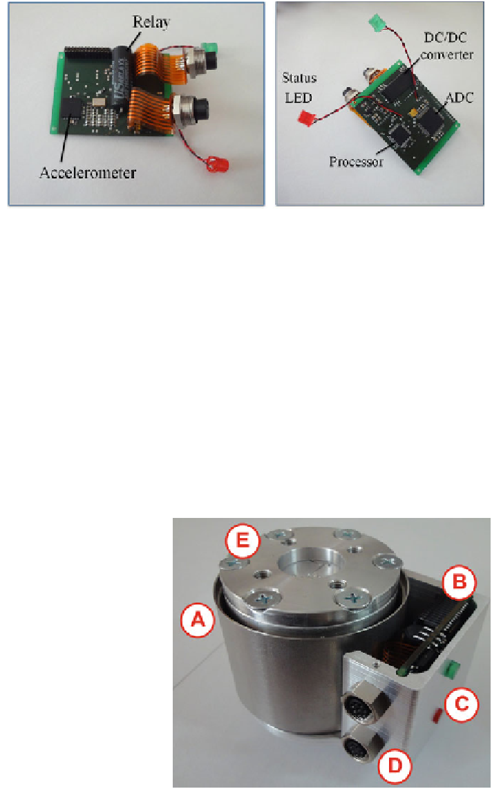
Fig. 6.3 The circuit board for the FTA sensor. a Top side: On this side the accelerometer (IMU)
and the relay for the emergency circuit are located. b Bottom side: The microprocessor, the
analog-digital converter and a two-staged direct current converter for power supply are placed on
this side
The second circuit provides the optional interfaces:
• USB connection for microcontroller programming, and
• two additional user I/O ports.
We have designed a specific casing for the FTA sensor as illustrated in Fig.
6.4
.It
protects the circuit board and provides the sockets for communication and power
supply. Additionally, the FT sensor is mounted onto the casing. Furthermore, the
casing allows easy application to the robot end effector. As FT sensor, we use a K6D
force-torque sensor (ME-Messsysteme GmbH, Heringsdorf, Germany). The sen-
sor's diameter is 40 mm and its height is 40 mm. The sensing range is up to 500 N
Fig. 6.4 The force-torque
sensor (A) is integrated in a
casing which houses the
circuit board (B) with the
embedded system and the
IMU. The casing also
includes the status and power
LEDs (C) and the two sockets
for communication (D). On
the FT sensors top side,an
adapter (E) for tool mounting
is located. The casing allows
for easy mounting to the
robot's end effector
Search WWH ::

Custom Search