Biomedical Engineering Reference
In-Depth Information
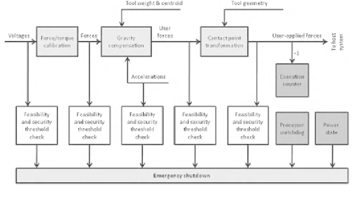
Fig. 6.2 The embedded system's monitoring cycle. All readings and calculations are checked in
each cycle. In case of an error the emergency shutdown is set instantly
6.1.3 Hardware Design: Circuit Board and Casing
In contrast to FT sensors, IMUs are available as Integrated Circuits (IC). There-
fore, we have designed a circuit board which hosts the IMU and the Microcon-
troller for the ES. As IMU, we use a three axes linear accelerometer with a
measurement range of up to
6 g,withg = 9.81 m/s
2
(LIS3LV02DQ; STMicro-
electronics SA, Plan-les-Ouates, Switzerland). As microcontroller, we use an At-
mel AT32 with a bandwidth of 32 bits and a processor clock rate of 60 MHz. The
processor has a programmable storage of 256 kB and a memory (Random-access
memory (RAM)) of 32 kB. Furthermore, an Analog-digital converter (ADC) is
located on the board for reading the voltages from the FT sensor. It provides eight
channels with a bandwidth of 24 bits and provides up to 32 kilo samples per
second (ksps). Additionally, the board consists of a direct current converter for
power supply. It converts the input voltages of roughly 24-5 V. We are using an
input voltage of 24 V as the Adept robot controller is operating with the same
input voltage and provides a 24 V user output. In this way, an additional power
supply unit is not needed. The relay for a galvanic isolated connection to the
emergency stop is also directly located on the board. Furthermore, the board
provides the sockets for communication and status Light-Emitting Diodes (LEDs).
Figure
6.3
shows the board's top and bottom side in detail.
The circuit board provides two external interfaces via the two sockets. The first
socket consists of the three main circuits for operation:
• 24 V power supply,
• emergency circuit, and
• serial communication (RS-232).
Search WWH ::

Custom Search