Biomedical Engineering Reference
In-Depth Information
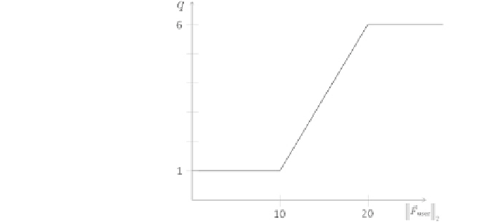
Fig. 5.3 Definition of the
factor q as a piecewise linear
function based on the
amplitude of user applied
force
position as the current stimulation point. Hereby, the stimulation point can be
automatically re-assessed for further investigations using the robot.
5.2.3 Contact Pressure Control
Contact pressure control keeps the coil on the head with a given pressure to assure
optimal coil placement as well as to avoid collisions with the head. In contrast to
manual coil positioning, we integrate the pressure control in the automatic robot
control and therefore consider two scenarios:
1. When the coil is approaching the target position, the pressure control provides
initial contact of the coil with the head.
2. During stimulation, pressure control keeps the contact of the coil to the head
and avoids impacts due to sudden head motion. The motion compensation
module keeps the coil in position when the head moves. Therefore, we combine
the pressure
control with the existing motion compensation module (see
The full process of contact pressure control, including both scenarios, is illustrated
in Fig.
5.4
.
5.2.3.1 Optimal Coil Placement
The process of optimal coil placement is shown in the upper part of the diagram in
Fig.
5.4
. For coil positioning at a given target position T , we use a virtual target
position T
0
30 mm above T . The TMS software calculates an optimal trajectory to
T
0
taking the current head position into account and moves the robot adapting to
the head's motion. The control software stops the robot movement and the control
loop in case of a collision or error, detected by increased FT recordings. When T
0
Search WWH ::

Custom Search