Hardware Reference
In-Depth Information
the template. Based on the calculation results, we search an appropriate threshold
for the correlation index (C
th
): if the correlation is larger than C
th
, we conclude that
there is a droplet in the cropped sub-image; otherwise, there is no droplet in the sub-
image. When the bioassay is running, we only need to crop the sub-images near the
expected positions of droplets, and calculate their corresponding correlation indices
to determine the absence/presence of droplets.
The advantages of the CCD camera-based sensing system are: (i) the identifica-
tion of the precise locations of the errors, and (ii) the detection of errors immediately
after they occur. One disadvantage of this system is that extra instruments, such as
CCD cameras, are required to observe the cyberphysical system.
The second sensing scheme is based on integrated optical detectors, as proposed
in [
15
,
16
]. By examining the concentration of the product in the droplets through
fluorescence, the quality of an intermediate product in a digital microfluidic biochip
can be determined [
15
,
16
].
When a fluorophore tag is attached to a droplet, different product concentrations
lead to the emission of light with different spectrum (i.e., different colors). This
difference in color can be detected by optical sensors that convert the received light
into electrical current or a voltage signal [
16
]. In recent work, integrated photodetec-
tors have been introduced on the microfluidic array [
15
,
16
]. For example, in [
15
], an
optical detection system was integrated with the digital microfluidic array. It consists
of a light-emitting diode (LED) and a photodiode which functions as light-to-voltage
converter. The concentration of products can be calculated according to the output
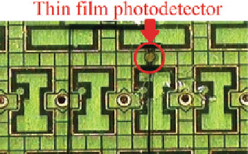
voltage of the photodiode. Another example, thin film InGaAs photodetectors can
be bonded onto a glass platform, coated with Teflon AF, and then integrated into the
digital microfluidic system. A coplanar digital microfluidic chip with the integrated
InGaAs photodetector is shown in Fig.
2.4
[
15
].
Even though no instruments with large footprint and precise alignment are
required in this method, the integrated optical detector-based sensing system has
a drawback that it cannot precisely locate the electrode where an error has occurred.
For example, when an output droplet of an operation is sent to the detector and
it fails to meet the requirement of the bioassay, we know that an error occurred
during the mixing operation, but we cannot locate the precise time and the position
where it occurred. The comparison between CCD camera-based sensing scheme and
detector-based sensing scheme can be found in Table
2.1
.
Fig. 2.4
Coplanar digital
microfluidic chip with
integrated thin film
photodetector [
15
]