Hardware Reference
In-Depth Information
190
nx_state <= WriteMinU;
191
when WriteMinU =>
192
RS <= '1';
193
DB <= bcd_to_lcd(minU);
194
nx_state <= WriteColon2;
195
when WriteColon2 =>
196
RS <= '1';
197
DB <= "00111010";
198
nx_state <= WriteSecT;
199
when WriteSecT =>
200
RS <= '1';
201
DB <= bcd_to_lcd(secT);
202
nx_state <= WriteSecU;
203
when WriteSecU =>
204
RS <= '1';
205
DB <= bcd_to_lcd(secU);
206
nx_state <= ReturnHome;
207
when ReturnHome =>
208
RS <= '0';
209
DB <= "10000000";
210
nx_state <= WriteHourT;
211
end case;
212
end process;
213
214 end architecture;
215 ------------------------------------------------------------
14.2 I
2
C Interface
I
2
C (Inter Integrated Circuit) is a synchronous eight-bit oriented serial bus for com-
munication between integrated circuits installed next to each other (normally on the
same board). Created by Philips in the 1980s, it is a two-wire bus with i ve standard-
ized speed modes, called
standard
(100 kbps),
fast
(400 kbps),
fast-plus
(1 Mbps),
high-
speed
(3.4 Mbps), and
ultrafast
(5 Mbps).
14.2.1 I
2
C Bus Structure
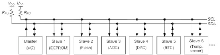
The I
2
C bus general structure is depicted in
i gure 14.6. Its two wires are called
SCL
(serial clock) and
SDA
(serial data), which interconnect a master unit to a number of
Figure 14.6
General I
2
C bus structure.