Graphics Programs Reference
In-Depth Information
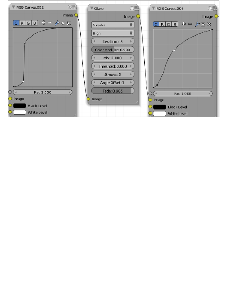
Now it's ime to work on the "A1A" row of nodes. Let's take a look at the corresponding
screenshot:
17. For this row, we need to add two
RGB Curves
nodes (
Add
→
Color
→
RGB
Curves
) and a
Glare
node (
Add
→
Filter
→
Glare
). Let's edit the curve for the "C"
channel of each
RGB Curves
node as shown in the previous screenshot and set the
parameters of the
Glare
node as follows:
Glare Type: Streaks
Quality: High
Iteraions: 5
Color Modulaion: 0.5
Mix: 0.0
Threshold: 0.0
Streaks: 5
Angle Offset: 1.0
Fade: 0.985
18. The connecions are as follows: Connect the image output of the "A1" row to the
image input of the first
RGB Curves
node, then connect the image output of the
first
RGB Curves
into the image input of the
Glare
node. Finally, connect the image
output of the
Glare
node into the image input of the second
RGB Curves
node of
this row. This way we get the "A1A" row complete.