Cryptography Reference
In-Depth Information
CONTRO
L
ancilla
pair
Φ
+
OUTPUT
TARGET
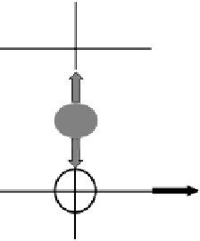
Figure 6.3
Controlled NOT gate using polarization-encoded qubits. The correct logi-
cal output is obtained whenever one and only one photon is detected in both detectors,
which occurs with a probability of
1
/
4
.
could be used to separate the photons along two different paths. Waveplates
could be used to rotate the plane of polarization of the photons, which cre-
ated a quantum superposition of logical states, where a horizontally polarized
photon represented a value of 0 and a vertically polarized photon represented
a value of 1. The parity check itself was implemented with a second polarizing
beam splitter, after which the state of polarization could be measured using
polarization analyzers and single-photon detectors. The results of the exper-
iment [7] are shown in Figure 6.6 for the case in which the input qubits had
definite values of 0 or 1. Here the large data bars correspond to correct results,
while incorrect results are seen to be relatively small. Similar performance was
also obtained using superposition states as inputs, which demonstrates the
quantum-mechanical coherence of the operation.
Another useful quantum logic gate is the quantum encoder [6] shown
in Figure 6.7. The intended function of this device is to copy the value of a
single input qubit onto two output qubits. Once again, this operation has to be
performed without measuring the value of the qubits. Our implementation of
a quantum encoder requires a pair of entangled ancilla photons in addition to
a polarizing beam splitter. The results from an experimental demonstration
[33] of a quantum encoder are shown in Figure 6.8. Once again, the error rate
can be seen to be relatively small.
It can be seen that the quantum parity check and encoder form the up-
per half of our CNOT gate shown in Figure 6.3. The operation of such a
device would require four single photons, two of them in an entangled state.