Cryptography Reference
In-Depth Information
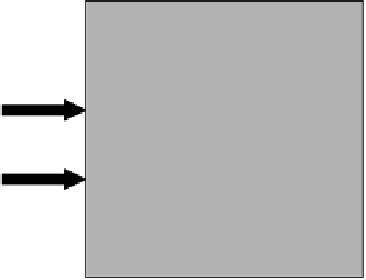
detectors
control
photon
OUTPUT
target
photon
ancilla
photons
Figure 6.2
Basic idea behind linear optics quantum logic gates. One or more ancillla
photons are mixed with two input qubits using linear elements. Postselection based
on measurements made on the ancilla will project the correct state of the two output
qubits. Feedforward control can be used to accept additional measurement results.
Figure 6.3. Its implementation requires only two polarizing beam splitters,
two polarization-sensitive detectors, and a pair of entangled ancilla used as
a resource. The correct logical output is obtained whenever each detector
registers one and only one photon, which occurs with a probability of
1
4
.
The CNOT gate shown in Figure 6.3 can be understood as the combination
of several more elementary gates, including the quantum parity check [6,32]
shown in Figure 6.4. The intended purpose of this device is to compare the
values of the two input qubits without measuring either of them. If the values
are the same, then that value is transferred to the output of the device. If the
two values are different, then the device indicates that the two bits were
different and no output is produced. A quantum parity check of this kind
can be implemented using only a single polarizing beam splitter and a single
polarization-sensitive detector.
An experimental apparatus [7] used to implement a quantum parity check
is outlined in Figure 6.5. Parametric down-conversion was used to generate
a pair of photons at the same wavelength. In type-II down-conversion, the
two photons have orthogonal polarizations, so that a polarizing beam splitter
/