Geology Reference
In-Depth Information
Air bubbles
Brine
pockets
Solid ice
Air bubbles
Drainage
channel
MY hummock ice
MY
melt pond ice
H2
FY ice
M1
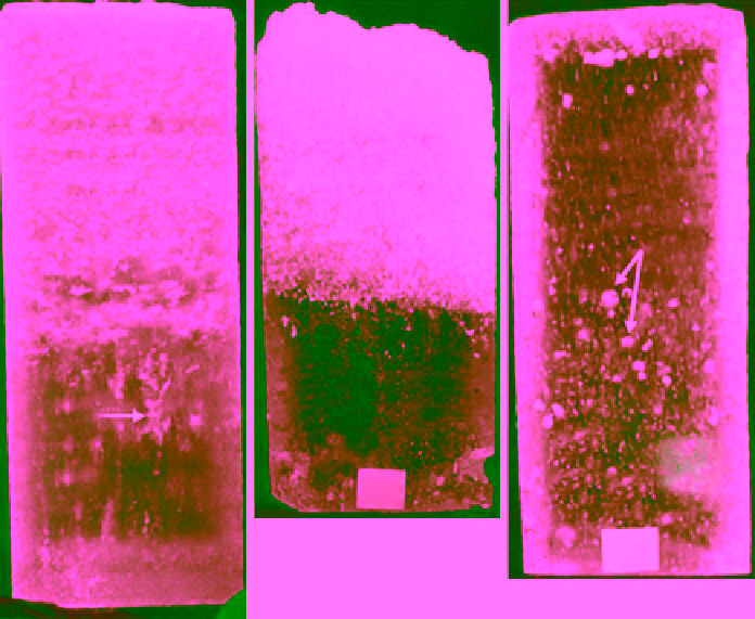
Figure 2.16
Three 100 mm diameter cores: FY ice, MY ice (hummock), and MY ice (melt pond); note brine drain-
age channels in the FY ice, porous top of layer of the MY hummock, and scattered air bubbles in the melt pond
(photographed by M. Shokr).
with or without solid precipitates, for temperatures higher
than about −40 °C, and particularly higher than about
−23 °C, as can be seen in the phase diagram, Figure 2.1.
This binary concept is used in modeling the thermal and
electrical properties of sea ice to be described in sec-
tion 3.6.2. It should be noted here that gas inclusions in
the form of very tiny air bubbles are commonly seen
inside the brine pockets in FY ice. While brine continues
to drain throughout the life time of FY ice, gas inclusions
remain trapped in the ice.
First‐year and old ice covers can be distinguished visu-
ally in the field based on the general topography of the
surface. The FY ice floes are usually flat, unless there are
ridges, which can be distinguished very clearly. On the
other hand, the undulating surface is the main discerning
feature of old, MY ice floes. These two types of ice can
be identified clearly by sampling ice cores or ice blocks.
The main discerning feature is the inclusion type (brine
pockets or air bubbles), which can be readily seen. The
geometric characteristics of the inclusions can be ascer-
tained readily by external examination of an ice core. In
fact, this is the only quick method for discriminating level
ice and melt pond ice in case of MY floes.
Figure 2.16 shows the top sections of three 100 mm
diameter cores extracted from a flat FY ice floe and from
a hummock and a melt pond in an MY floe in Parry
Channel near Resolute in May 1993. The cores were
photographed after cutting each core vertically into two
halves along its center. The photograph of the FY ice
shows the intensive brine inclusions that gives the core
a “foggy” appearance. It shows also a brine channel with
its converging tributaries. The white top of the old hum-
mock ice exhibits the highly porous subsurface layer that
actually triggers the high radar backscatter values, which
distinguishes MY from other types in radar remote sens-
ing imagery (section 8.1.1). Note the sharp transition
between the bubble‐rich area at the top of the core and
the clear area below. Melt pond ice, on the other hand,
features scattered air bubbles that are much less in num-
ber and size. These inclusions may originate in superim-
posed ice discussed earlier in section 2.2.3. The latter
probably forms from the freezing of snow‐clogged water at
the surface of the melt pond. This layer is usually followed
by relatively clear ice, which represents either the original
MY or newly frozen ice from freshwater accumulated in a
melt pond with no snow nucleation. In general, air bub-
bles in MY ice are much larger than brine pockets in FY
ice, with their major axis in the order of a few millimeter
compared to a millimeter or less in length of brine pock-
ets [
Bjerklund et al.,
1985;
Perovich and Gow,
1996].
The landmass in the Arctic is full of numerous fresh-
water lakes. Bubbles in the lake ice are formed when the