Hardware Reference
In-Depth Information
Figure
11-1
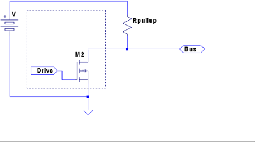
shows a simplified schematic of the master attached to the bus. Some
voltage V (typically, +5 V) is applied to the 1-Wire bus through the pull-up resistor
R
pullup
.
When the transistor
M
2
is in the Off state, the voltage on the bus remains high because of
the pull-up resistor. However, when the master device activates transistor
M
2
, current is
caused to flow from the bus to the ground, acting like a signal short-circuit. Slave devices
attached to the bus will see a voltage near zero.
Figure 11-1.
1-Wire driver circuit
■
Note
the raspbian Linux 1-Wire bus uses GpiO 4 (GpCLK0) pin p1-07.
Likewise, when a slave is signaled to respond, the master listens to the bus while
the slave activates its driving transistor. Whenever all driving transistors are off, the bus
returns to the high idle state.
The master can request that all slave devices reset. After the master has made this
request known, it relinquishes the bus and allows it to return to the high state. All slave
devices that are connected to the bus respond by bringing the line low after a short
pause. Multiple slaves will bring the line low at the same time, but this is permitted. This
informs the master that at least one slave device is attached to the bus. Additionally, this
procedure puts all slaves into a known reset state.
Master and Slave
The master device is always in control of the 1-Wire bus. Slaves speak only to the master,
and only when requested. There is never slave-to-slave device communication.
If the master finds that communication becomes difficult for some reason, it may
force a bus reset. This corrects for an errant slave device that might be jabbering on the
line.