Hardware Reference
In-Depth Information
89 gpio_read(int gpio) {
90 unsigned sel = 1 << gpio;
91
92 return (GPIO_GET) & sel ? 1 : 0 ;
93 }
94
95 /
End gpio_io.c
/
∗
∗
GPIO Transistor Driver
The GPIO pins on the Pi are often going to be pressed into driving something in the
outside world. GPIO pins 28 to 31 can drive up to 16 mA, maximum. The remaining
GPIO pins are configured to drive up to 8 mA. These are fairly weak interfaces to the
outside world.
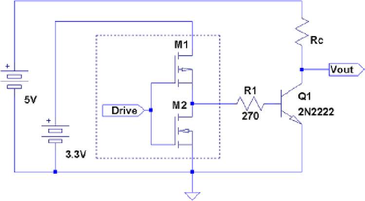
Sometimes all that is needed is a simple one-transistor buffer. The 2N2222A
transistor is cheap and drives a fair amount of current. Figure
10-8
shows a simple driver
circuit attached to a GPIO output pin.
Figure 10-8.
2N2222A driver
The GPIO output driver sees only a diode-like path to ground through the base of
transistor
Q
1
. Resistor
R
1
is chosen to limit that current.
The resistor shown as
Rc
in the figure represents the load, like a high-current LED in
series with a current-limiting resistor. Alternatively, it may be a resistor chosen so that the
Vout
represents a stiffer output voltage.
In the diagram, the resistor
R
c
is connected to the +5 V power supply. This is safe
because current
cannot
flow from the collector into the base of
Q
1
. This prevents 5 V
from flowing into the GPIO pin (that junction is
reversed
biased). Thus
Q
1
allows you to