Image Processing Reference
In-Depth Information
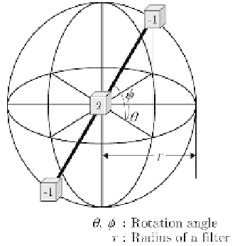
Fig. 3.3.
A 3D simple difference filter. This figure shows a second-order difference
filter. A first-order difference filter is obtained by making a center weight to be zero.
Remark 3.9.
Omnidirectionalization results of the rotational-type filters men-
tioned above are called
rotational difference filter
. Results were applied to 3D
chest CT images to detect lung cancer [Shimizu93, Shimizu95a, Shimizu95b].
Several examples are:
g
(
p
)
ijk
g
(
p
)
ijk
(
r
)=max
(
θ,φ
)
{
(
r, θ, φ
);
0
<θ,φ
≤
π
}
.
(3.42)
g
(
p
)
ijk
g
(
p
)
ijk
(
r
)=min
(
θ,φ
)
{
(
r, θ, φ
);
0
<θ,φ
≤
π
}
.
(3.43)
(
r
)=
θ
g
(
p
)
ijk
g
(
p
)
ijk
(
r, θ, φ
)(
p
=
1
,
2
)
.
(3.44)
φ
3.3.7 3D Laplacian
A 3D Laplacian is derived naturally from the sum of the output of three
second-order difference filters as is shown below, or of the sum of all outputs
of the first-order difference filters for all directions.
g
ijk
=
f
i
+
r,j,k
+
f
i,j
+
r,k
+
f
i,j,k
+
r
+
f
i−r,j,k
+
f
i,j−r,k
+
f
i,j,k−r
−
6
f
ijk
.
(3.45)
Representations by masks are shown in Fig. 3.4 for
r
=
1
, and other variations
are given in Table 3.1 and 3.2.
3.3.8 2D difference filters and their combination
New types of 3D filters are derived by calculating a suitable function of outputs
of 2D filters on two parallel planes placed on the opposite side of a voxel
Search WWH ::

Custom Search